
1.What Is Hole & Dimension Metrology?
Hole and dimensional metrology involves measuring the size, shape, and location of physical features. In PCB manufacturing, it supports process checks, assembly fit verification, and final inspection.
Several measurements may describe the same hole, but they answer different questions:
- Hole diameter: How large is the opening at the defined measurement location?
- Hole spacing: What is the distance between specified hole centers?
- Hole position: Where is the hole relative to the drawing’s reference system?
- Hole form: Does the hole meet the specified shape requirement?
- Hole-to-edge distance: How does the hole relate to the board outline?
2.Turn PCB Drawing Requirements into a Measurement Plan
Distinguish Drilled Holes from Finished Holes
A drilled-hole requirement applies to a different process stage from a finished-hole requirement. For plated through-holes, subsequent processing changes the internal surface.
Separate Size from Geometric Requirements
A diameter tolerance controls a size characteristic. A position requirement relates the feature to its specified reference system. Additional controls may address shape or orientation.
Use a simple inspection plan to keep these requirements separate:
| Feature | Requirement to identify | Measurement approach to evaluate | Record to retain |
|---|---|---|---|
| Finished hole | Diameter limits and measurement definition | Suitable optical or contact method; approved gauging where applicable | Result, location, method, and process stage |
| Hole pattern | Coordinates, spacing, or position relative to datums | Coordinate-based measurement | Datum setup and feature results |
| Slot | Width, length, location, and any form requirements | Appropriate vision or coordinate measurement | Measured features and evaluation settings |
| Board outline | Dimensions and any profile requirements | Measurement against the specified reference system | Outline results and deviations |
| Hole-to-edge relationship | Defined hole and edge references | Measurement in a common coordinate system | Reference definitions and distance results |
3.How to Measure PCB Hole Diameter?
Measure PCB hole diameter using a method suited to the hole size, manufacturing stage, and drawing requirements. Confirm whether the specification applies to a drilled hole or a finished hole after plating.
- Check the inspection requirement. Identify the hole, diameter limits, and required measurement location. The visible hole opening may not represent the diameter throughout its depth.
- Prepare and support the board. Inspect for debris, burrs, or damage. Use approved cleaning procedures and support the PCB without distorting it. Do not remove material merely to obtain a passing result.
- Select the measurement method. A suitable vision system can measure visible hole boundaries. Approved pin or plug gauges can check specified size limits. Internal measurements require equipment compatible with the hole diameter and depth.
- Perform the measurement consistently. For optical measurement, control lighting, focus, edge detection, and fitting settings. For gauging, follow the prescribed insertion procedure and never force the gauge.
- Record and evaluate the result. Document the hole identifier, process stage, method, result, and acceptance limits. Retain measurement images where useful, and investigate inconsistent or borderline results before acceptance.
A hole-diameter check does not establish hole position, full internal geometry, or copper-plating thickness. These require separate inspection tasks.
4.How to Measure PCB Hole Position and Hole Spacing?
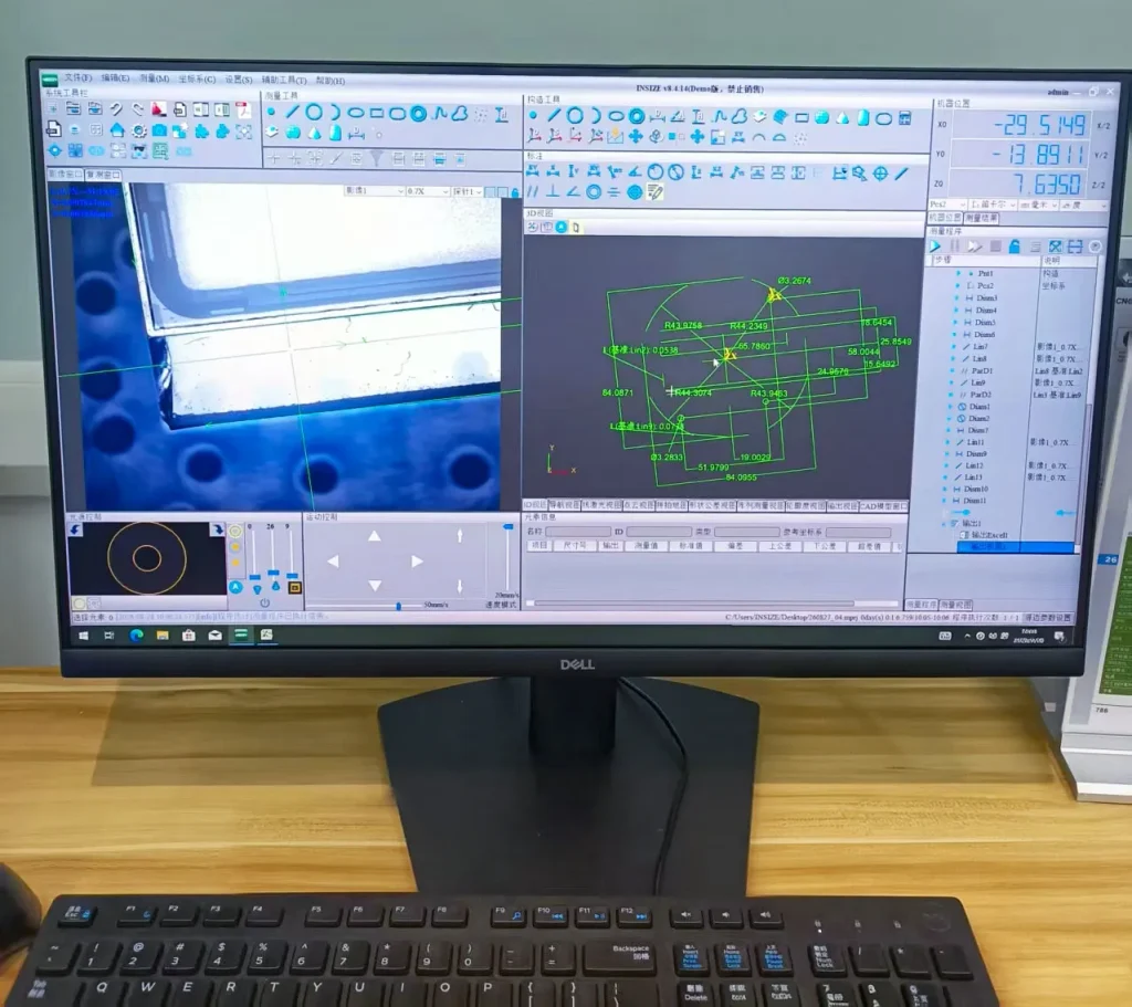
Measure PCB hole position and spacing within the reference system specified on the drawing. Hole position describes a hole’s location relative to datums, while hole spacing usually describes the center-to-center distance between selected holes.
- Confirm the drawing requirements. Identify the holes, dimensions, tolerances, and datum features. Distinguish coordinate dimensions from geometric position requirements.
- Support and align the board. Hold the PCB under the specified inspection conditions without introducing unintended distortion. Establish the coordinate system from the required datums rather than convenient edges.
- Measure the hole features. Use a suitable vision or coordinate measuring system to acquire the hole boundaries and determine their centers. Keep sampling and fitting settings consistent.
- Evaluate position and spacing separately. Compare hole locations with the drawing requirements. For spacing, calculate the specified center-to-center distance—or its X or Y component, if that is what the drawing controls.
- Record and verify the results. Document the datum setup, measured coordinates, distances, tolerances, and evaluation method. Repeat the setup when checking positioning consistency.
Correct hole spacing does not prove correct hole position: an entire hole pattern can be displaced while the distances between its holes remain unchanged.
5.How to Choose Hole and Dimensional Measurement Equipment?
Choose equipment around the feature and its tolerance, then check whether the method works on the actual PCB.
Part size, access, rigidity, surface condition, and required inspection time all affect the decision. A high-resolution display does not establish that a system can evaluate the feature adequately.
| Equipment or method | Potential use | Result it can provide | Main limitation to check |
|---|---|---|---|
| Vision measuring system | Visible hole boundaries, hole patterns, slots, and outlines | Dimensions and coordinates from detected features | Illumination, edge definition, focus, and internal visibility |
| Appropriate pin or plug gauges | Defined hole-size limit checks | Acceptance information under the prescribed procedure | No independent hole-position result or complete form description |
| Contact coordinate measurement | Accessible geometric features and their relationships | Coordinates and evaluated dimensions | Probe access, contact force, and board support |
| Suitable bore-measuring instrument | Accessible internal diameters | Measurements at supported locations | Minimum hole size, depth access, and contact geometry |
| Tactile imaging or other specialized methods | Application-specific surface and hole features | Method-dependent geometry data | Sensor access, contact effects, and validated feature range |
A coordinate measuring machine can evaluate geometric features from measured points, but its suitability for a particular PCB depends on the probe and workholding arrangement. It should not be selected solely because it is regarded as a precision instrument.
6.Measurement Errors, Calibration, and Repeatability
Consistent readings do not automatically mean accurate measurements. A PCB hole can produce repeatable results that are biased by incorrect edge detection, unsuitable contact conditions, or an improper reference setup.
Common sources of measurement variation include:
- Sample condition: Debris, burrs, plating irregularities, and damaged edges.
- Positioning and support: Different clamping forces, board deflection, or inconsistent datum alignment.
- Measurement settings: Lighting, focus, probe contact, sampling locations, and fitting methods.
- Environmental conditions: Temperature changes affecting the board or measuring equipment.
Calibration establishes the relationship between instrument readings and reference values under specified conditions. Routine verification checks whether the measurement system continues to meet defined requirements. Adjustment, when needed, is a separate action.
7.Hole & Dimension Metrology FAQ
Can a pin gauge measure hole position?
A pin gauge used alone does not establish a hole’s position relative to drawing datums. Position inspection requires an appropriate reference and measurement arrangement.
Can optical measurement verify the entire hole interior?
Not from a visible opening alone. Internal geometry requires suitable access and a method validated for the required depth and feature.
Can a copper thickness probe measure hole diameter?
Do not assume so. Hole-wall copper thickness and hole diameter are different quantities. A copper-thickness instrument’s capability does not establish dimensional measurement capability.
Are locating pins interchangeable with inspection gauges?
No. A locating pin’s intended role is positioning. Using it for acceptance inspection requires appropriate dimensional requirements, verification, and an approved procedure.
Does a matching CAD overlay prove dimensional conformity?
A visual overlay can help identify differences, but conformity depends on the specified dimensions, datums, tolerances, and measurement method. Apparent alignment on screen is not enough to establish that every requirement has been met.
 Russian
 English
 German
 French
 Spanish
 Vietnamese