
What Does an Ionic Contamination Tester Measure?
Ionic Contamination Tester(Ionic Contamination Meter) utilizing the Resistivity of Solvent Extract (ROSE) test method defined in IPC-TM-650 Method 2.3.25, remains the industry-standard frontline tool for quantifying total extractable ionic residues on bare boards and assembled circuit cards.Testers come in static and dynamic types, offering precise measurement to meet strict industry standards.
Types of Ionic Contamination Testing Equipment
Static Volumetric Testers
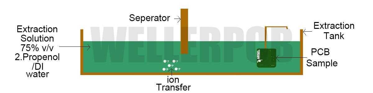
Static systems utilize a fixed volume of test solution (typically a mix of Isopropyl Alcohol and Deionized Water). The PCB is submerged, and the ionic species are extracted into the solution. The Ionic Contamination Tester then measures the total change in resistivity. This method is straightforward and highly effective for standard quality checks.
Dynamic Monitoring Systems
A more advanced Ionic Contamination Monitoring System uses a continuous flow of solution. As the liquid circulates through the test chamber and over the board, the system monitors the extraction rate in real-time. This dynamic ionic contamination test method is often more sensitive and can provide a “cleanliness curve,” showing how quickly contaminants are being removed.
What IPC-TM-650 Means for PCB ROSE Testing
The ROSE Tester measures the change in electrical conductivity of a specialized solvent bath as ionic species are dissolved off the test article.
IPC-TM-650 contains individual test methods. A purchase specification should identify the method and revision rather than simply request an “IPC-compliant tester.”
[ PCB Sample ] ---> Submerged in IPA/DI Water Bath ---> Dissolves Ionic Residues ---> Measures Conductivity Shift
A. The Solvent Extraction Blend
The standard testing solution consists of a volumetric mixture of high-purity Isopropanol (IPA) and Deionized (DI) water (typically a 75% / 25% or 50% / 50% ratio depending on specific test standards). Isopropanol lowers the surface tension of water, allowing the solvent to penetrate narrow component standoffs and under-fill gaps while dissolving both polar and non-polar residues.
B. Evolution of Cleanliness Standards
Historically, electronics manufacturers relied on a rigid pass/fail threshold of 1.56μm/cm² NaCl equivalent. Modern revisions under IPC-J-STD-001 shift the compliance philosophy toward objective process control. Rather than treating 1.56μm/cm² as a universal ceiling, manufacturers must establish statistical process control (SPC) limits based on their specific flux chemistries, conformal coating requirements, and operational environments.
How to Choose an Ionic Contamination Tester
Start with the samples and the required procedure. A large tank or detailed display does not automatically make an instrument suitable.
| Selection item | What to confirm |
|---|---|
| Sample capacity | Usable dimensions, component height, holder clearance, and permitted sample loading |
| Method implementation | Supported procedure, extraction conditions, endpoint, and relevant documentation |
| Measurement capability | Working range, verification performance, and behavior near the required decision level |
| Result calculation | Area input, units, calculation settings, and treatment of multiple samples |
| Data records | Sample identification, recipe, timestamps, raw or trend data where available, and export |
| Maintenance and support | Consumables, cleaning instructions, calibration support, and service availability |
If multiple boards can be tested together, confirm how the combined result is calculated and whether it answers the inspection question. A batch result may not reveal which board contributed the contamination.
Static and dynamic systems should be evaluated against the intended method and application. Do not rank one as universally superior or assume results will match merely because the displayed units are identical.
A Practical ROSE Test Workflow
Use the following sequence to develop a controlled procedure. Exact settings must come from the applicable method and equipment documentation.
Identify and protect the sample
Record the board or assembly identifier, process stage, cleaning history, and sampling reason. Handle and package samples using the approved contamination-control procedure.
Do not clean a sample immediately before testing unless that cleaning is part of the defined study. Otherwise, the measurement may no longer represent the process being investigated.
Confirm instrument readiness
Check maintenance status and complete the required calibration, verification, and background checks. These serve different purposes: calibration establishes the measurement relationship, verification checks performance, and a blank helps evaluate the test background.
Confirm the recipe and area
Review the extraction liquid, temperature conditions, test endpoint, sample loading, units, and area definition. Record the procedure revision.
Run and document the test
Load the sample using the specified holder and procedure. Preserve the result, any available measurement curve, and equipment warnings.
Control the sample after testing
Identify the sample as tested and follow the approved drying and disposition procedure. Confirm component compatibility and whether tested assemblies may return to production before using saleable product.
Surface Area Calculation and Sample Preparation Protocols
Accurate cleanliness reporting requires precise mathematical input of the test article’s total surface area (Atotal).
Area Calculation: A_total = 2 × (Length × Width) + Component Top/Side Surface Areas
A. Surface Area Modeling (Atotal)
Testing operators must account for both sides of the board. For complex assemblies, the calculation must factor in component body surface areas, lead count geometries, and multi-layer internal board dimensions if bare boards are audited. [Data to be added: specific area-weighting algorithms for high-density 3D BGAs]
B. Pre-Test Handling and Contamination Prevention
Operators must wear powder-free cleanroom gloves or finger cots when handling test articles. Skin oils and sweat introduce massive quantities of sodium and chlorine ions, immediately invalidating the baseline cleanliness reading.
C. Blank Run Verification
Before testing a production batch, the instrument must execute a baseline blank cycle to confirm that the extraction solvent has returned to its required purity threshold.
ROSE Testing vs. Ion Chromatography (IC): Analytical Comparison
| Analytical Parameter | ROSE Testing (IPC-TM-650 Method 2.3.25) | Ion Chromatography (IPC-TM-650 Method 2.3.28) |
| Primary Output | Total ionic contamination expressed as μm/cm² NaCl equivalent | Identification and concentration of specific ions (Cl-, Br-, SO42-, etc.) |
| Test Speed | Rapid (5 to 15 minutes per cycle) | Slow laboratory analysis (1 to 2 hours per sample) |
| Primary Use Case | Routine line auditing, SMT process control, incoming QC | Failure analysis, electrochemical migration (ECM) root cause investigation |
| Limitation | Cannot identify which specific ion caused the spike | High equipment cost; requires specialized lab technicians |
While ROSE testing provides rapid bulk quantification, high-reliability aerospace and medical applications often require advanced chemical speciation.
Assessing Electrochemical Migration (ECM) Risk
ROSE testing flags overall ionic load, but certain ions (particularly chloride Cl- and bromide Br﹣) are far more aggressive in triggering electrochemical migration and dendritic growth under high humidity and DC voltage bias. When ROSE limits are exceeded, IC analysis is the necessary next step.
Troubleshooting High Ionic Contamination Failures on SMT Lines
When an ionic contamination tester flags a production lot for excessive residue, a structured troubleshooting workflow must be deployed.
A. Tracing Flux Residues and Activator Breakdown
- Incomplete Curing / Reflow: If thermal profile peaks are too low or dwell times too short, rosin or water-soluble flux activators fail to fully decompose, leaving aggressive corrosive chemical residues.
- Resin Saturation: Check whether wave soldering flux sprayers are dispensing excessive flux volumes.
B. Cleaning Equipment Optimization
For lines utilizing inline aqueous or solvent cleaning systems, verify the Sinner Circle parameters: chemical concentration, wash temperature, mechanical spray pressure, and conveyor speed. High ionic readings often stem from exhausted wash bath DI water filters or depleted detergent chemistry.
C. Environmental and Operator Factors
Audit handling stations for airborne contaminants, sweat transfer, or improper storage bins that introduce ionic salts prior to final packaging and test.
 German
 English
 French
 Spanish
 Vietnamese
 Russian