Pressure foot ring for PCB
$0.1 – $0.2
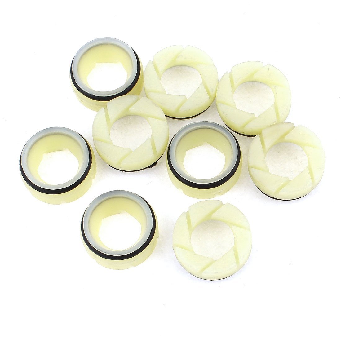
pressure foot ring is a critical contact component in a CNC PCB drilling machine that applies downward pressure to the board stack, ensuring material flatness and stabilizing the workpiece against high-speed spindle vibrations.
What is a Pressure Foot Ring?
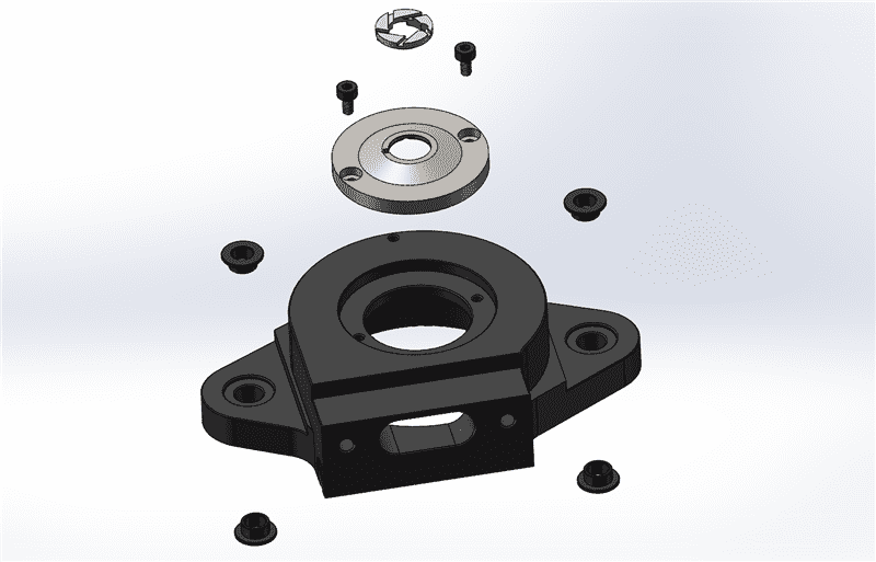
In a CNC PCB drilling machine, the pressure foot assembly is the interface between the high-speed spindle and the PCB stack. Its primary job is to clamp the stack firmly against the machine bed before the drill bit touches the surface.
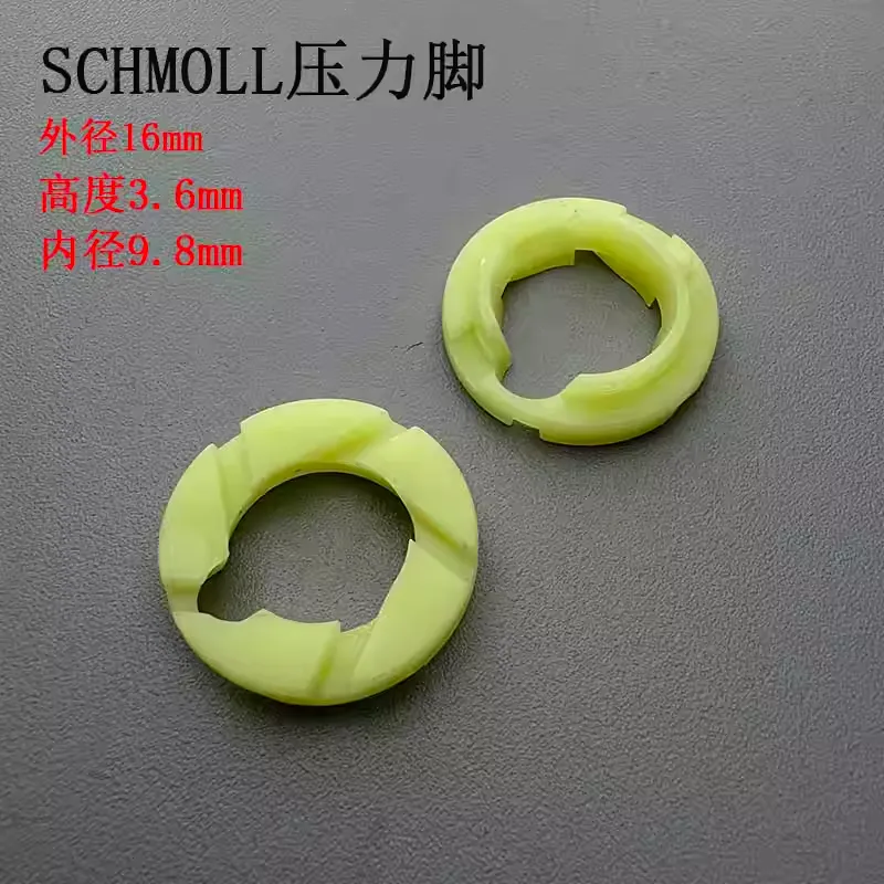
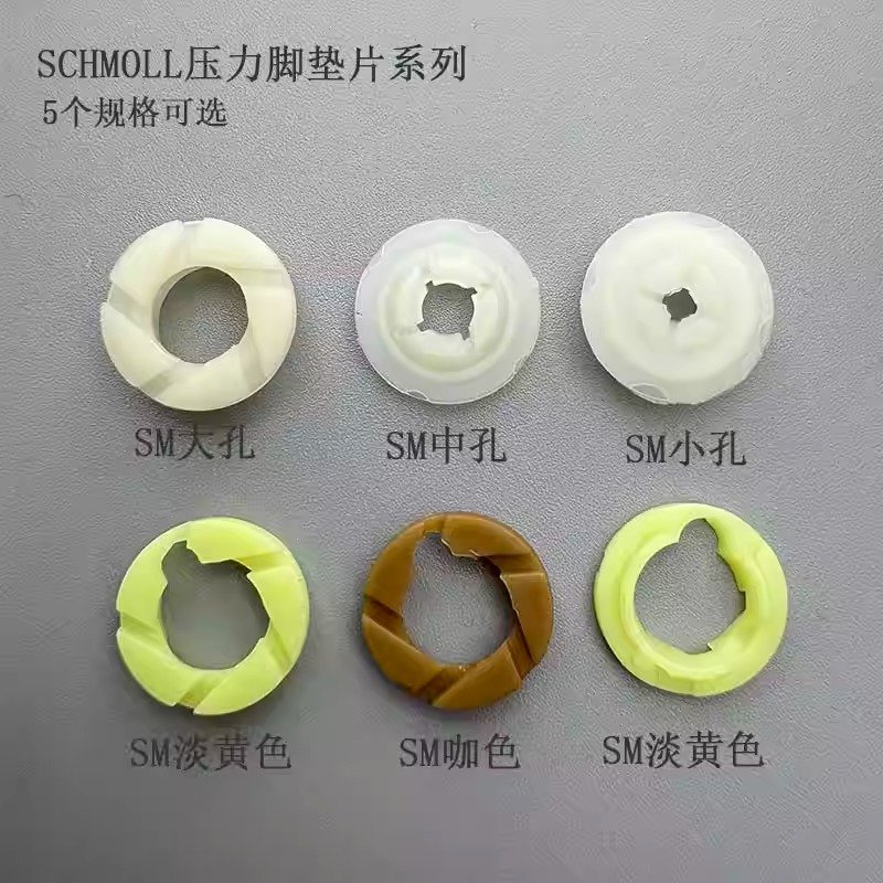
The pressure foot ring (often referred to as the SM pressure foot insert in certain configurations) acts as the contact point. It ensures that the entry material and the PCB laminates do not vibrate or lift during the high-speed entry and exit of the drill bit. Without a high-quality yellow pressure foot ring or its equivalent, the risk of “burring” or “nailheading” increases significantly, potentially scrapping expensive multi-layer boards.
The Schmoll Standard: Engineering for 125k RPM and Beyond
When discussing top-tier PCB drilling, Schmoll Maschinen is often the industry benchmark. Their machines require specialized components designed to handle extreme centrifugal forces and thermal loads.
Schmoll Pressure Foot Ring and Inserts
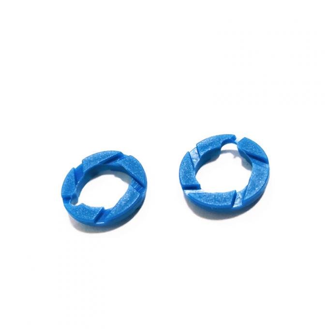
The Schmoll pressure foot ring is engineered to withstand the rigorous vibrations of 24/7 production. Manufacturers often choose between different materials—such as specialized polymers or hardened alloys—depending on the substrate being drilled. Using a genuine or high-quality compatible Schmoll pressure foot insert ensures that the clamping pressure is distributed evenly around the drill bit, preventing localized deformation of the board.
The Role of the Pressure Foot Bush
While the ring handles the contact, the pressure foot bush provides the guidance. In Schmoll systems, the Schmoll pressure foot bush acts as a sleeve that aligns the pressure foot housing. For ultra-high-speed spindles, the Schmoll 125k rpm pressure foot bush is specifically balanced to ensure that no harmonic vibrations interfere with the spindle’s path.
Critical Performance Factors: Inserts and Bushes
Choosing the right pressure foot insert or pressure pressure foot bush involves analyzing several technical variables that impact the “Total Cost of Ownership” (TCO) in a smart factory.
Material Science and the “Yellow” Standard
You will often see the yellow pressure foot ring in high-end facilities. This specific color-coding usually denotes a particular durometer (hardness) or material composition designed for high-abrasion resistance. These rings are optimized to:
Minimize Friction: Reducing the heat buildup between the foot and the entry foil.
Maximize Suction Efficiency: The internal geometry of a pressure foot insert is designed to allow the vacuum system to remove chips effectively, preventing “re-cutting” of debris.
Precision Alignment
A pressure foot bush that is worn or out of spec will cause the entire foot assembly to tilt. Even a 0.01mm deviation can lead to “skewed” holes. High-precision Schmoll pressure foot bush replacements are manufactured to micron-level tolerances to maintain perfect perpendicularity to the machine table.
Maintenance and Replacement Cycles
In a high-volume CNC machining China factory, the pressure foot assembly is considered a “consumable” system, but that doesn’t mean it should be ignored.
Inspection: The pressure foot ring should be inspected for “scoring” or uneven wear every shift. A scored ring can scratch the entry foil, leading to debris being forced into the hole.
Cleaning: Resin buildup inside the pressure foot insert can restrict airflow. Ultrasonic cleaning is recommended to maintain vacuum efficiency.
Bush Replacement: The Schmoll pressure foot bush should be checked for “slop” or play. If the housing can wiggle, the bush has reached its end of life and will begin to degrade the accuracy of your high precision cnc machining parts.
Why the Pressure Foot System is Vital for 2026 PCB Trends
As we move deeper into 2026, two major trends are dominating PCB fabrication: High-Density Interconnect (HDI) and High-Frequency (5G/6G) boards.
HDI Drilling: With micro-vias becoming smaller, the “clamping zone” provided by the SM pressure foot insert must be perfectly flat. Any gap allows the board to flex, which snaps micro-drills instantly at speeds exceeding 200,000 RPM.
Specialty Materials: PTFE and ceramic-filled high-frequency boards are prone to “smearing.” A properly tuned Schmoll 125k rpm pressure foot bush ensures that the vacuum suction is maximized through the pressure foot ring, pulling heat and dust away from the hole immediately.

")

")


")